Quantcast
Channel: Clippard Knowledgebase - Applications
Viewing all 132 articles
Browse latest View live

Precision Control for MicroBlasting

$
0
0
Category: 

Clippard Pneumatic Solutions

Clippard Pneumatic Solutions


As micro-abrasive blasting becomes more and more sophisticated, manufacturers are continuing to develop equipment for a wider range of intricate processes used in many industries. Some of those industries include medical, precision machining, aerospace, semiconductor and more.

Clippard Micro Blasting Application


micro blasting

Micro blasting describes the process of delivering micron sized abrasives by means of compressed air or gas to the surface of an object. This process demands a very precise means of control—not only in volume, but in speed, distance from the part, and other variables depending on the base material. Although manufacturers offer many types of blasting machines, most are delivered through a very small nozzle. The orifice of the nozzle will vary depending on the blasting material, but the small nozzle size enables the micro blasting of precision parts for medical pacemakers, texturing surfaces for adhesives, or the cleaning/de burring of very small parts, just to name a few.


Clippard Micro Blasting Application

controlled delivery

Comco, Inc., located in Burbank, California, recently introduced their AccuFlo micro blaster. Their patented PowderGate valve controls the on/off action of the abrasive material. This control process utilizes Comco's patented Simoom Technology. As applied to AccuFlo, Simoom Technology describes how the modulator, media tank and mixing chamber work together for a controlled delivery of the abrasive.


quality & precision

Housed in the control panel is one of Clippard's Minimatic® stainless steel cylinders, which was designed and built for this particular application. The function of the cylinder in the delivery process is to precisely open and close the PowerGate valve. Working in concert with the distributor and Comco Inc., Clippard's application engineering was able to meet the design criteria and quality needed for this micro blasting process.


Download Whitepaper (PDF)
Locate a Distributor
Request Literature


Related Products:

Stainless Steel Cylinders   


Pneumatic Solutions for Ride Control

$
0
0
Category: 


Ever experience the bone jarring, teeth rattling pounding from riding in a boat? Pounding so abrupt and hard you just know your lumbar spine was hammered closer to your cervical spine? The times when you felt like you needed to say to your friends you had a great time, but in truth you were glad to be back on land? Now, imagine going even faster—hitting the waves even harder, and with more frequency...


Gliding on Waves

 
greater safety & control

Covering the vast coastlines of our waterways, the military must at times endure the extreme harshness of fast speed and unnerving demands for control. In order to provide greater safety and control, Clippard's value added team, working in concert with Shockwave engineers, has developed a custom engineered system that provides a much safer, smoother ride.
 

Shockwave Seats, a division of Professional Components, Sidney BC, Canada, has developed products that have been used in numerous markets, including; military and law enforcement, rescue and patrol, racing and performance, cruising and fishing, and much more. According to president David Smith, Professional Components was awarded the single largest shock mitigation seat contract by the United States Coast Guard to supply seats for Homeland Security patrol vessels.
 

"The Coast Guard wanted a simple solution to enable them to adjust the air shock absorber for varying payloads and sea conditions. We had a rough idea of what we needed and built a crude working prototype. Clippard took the idea and ran with it, and within a short period of time we had the slick, robust version we call the RCC or Ride Control Center.The Coast Guard likes it, and we have enjoyed our working relationship with Clippard."


custom engineered

It is a very straight forward solution. First, the system is pressurized by pumping the stainless steel cylinder the necessary number of times to allow for the weight of the passenger. It is then locked (stowed) in position. From here, it is a matter of personal preference as far as the cushion of the ride is concerned—the easily accessible ride control valve enables the passenger to adjust the amount of air/ how fast the air can pass through the air volume tank. The more air that is allowed to escape, the more cushy the ride.
 

Clippard's control system includes a stainless steel cylinder, special aluminum manifold, four cartridge stem valves, a ride control valve, mufflers, knobs, and a pressure gauge.


Contact Clippard Contact Clippard
Locate a Clippard Distributor Locate a Distributor


Related Products:

Stainless Steel Cylinders

Value-Added Services

Clippard Value-Added Services


Case Study: Liquid Level Sensing

$
0
0
Category: 

CASE STUDY

liquid level sensing

Oil & Water Blend!

Separating oil, gas and water from a tank can be a real challenge. This is especially true when all three are in a tank that is continually building internal pressure.


How to control the pressure and allow for the separation of the three was the challenge faced by designers at Clippard Instrument Laboratory. Their Value Added team’s answer is the VA-1164 liquid level controller. This straightforward and original design includes several standard Clippard parts as well as parts manufactured specifically for the unit. 

The specially-designed block manifold houses an MPS-2 sensor, three cartridge valves, two pressure gages, and a stainless steel micron filter. In addition, a sight glass is attached to the block that allows for easy inspection of the set point.

Cordova Flow Controls, Greely, Colorado, describes the VA-1164 as a standalone no-bleed level control head used to replace common cantilever or torque tube level control heads that either don’t perform consistently, or are high-bleed controllers.

Operation of the VA-1164 controller is actuated by a float inside the separation tank. As the liquid rises, the float moves a rod that touches the pilot actuator valve which sends signal to a cylinder that opens a valve that release liquid from the tank. The challenge is to keep the tank level allowing for continuous flow of gas, which also brings some water and oil from the source.

One of the features of the VA-1164 is the no-bleed design, whereas previous models constantly bleed gas, meaning it is environment friendly. Another is the sight glass which not only provides for immediate visual inspection, it also prevents dust from getting into the sensing area. The VA-1164 also includes a stainless steel filter at the supply connection, a manual override and a threaded port for venting or piping away exhaust.

With ease of installation, accuracy, durability and cost effective operation, the VA-1164 is a true value added controller for many applications.


Clippard Liquid Level Controller


Contact Clippard Contact Clippard
Locate a Clippard Distributor Locate a Distributor
Download PDF Download Whitepaper (PDF)


Related Products:

Stainless Steel Cylinders

Value-Added Services

Clippard Value-Added Services


Case Study: Safe Braking Systems

$
0
0
Category: 


CASE STUDY

safe braking systems

A system responsible for applying the brakes in a vehicle being towed must be able to apply the brakes safely and reliably—ideally, exactly as if the vehicle were being driven.


Clippard Instrument Laboratory, Inc., Cincinnati, Ohio and Isaacs Fluid Power, Indianapolis, Indiana, have been working in concert with SMI Brake, Newburg, Indiana, to provide solutions for braking a towed vehicle.

SMI now offers three solutions that enable the safe braking of a vehicle being towed by a motor home; Air Force One, Stay-In-Play Duo and Delta Force. All three systems are not only safe and reliable, but according to SMI, they are economical and offer the best warranty in the business.

Air Force One operates by using a small amount of air from the motor homes’ air supply to create the necessary vacuum to operate the towed vehicle’s power brake system and drive the brake actuator. True proportionate braking is achieved as a result of the direct connection. This supplemental system is also touted as one that provides true coach protection with a patent pending breakaway system which seals the coach’s air supply in the event of a separation. According to SMI, this protection kit is the only DOT compliant and chassis approved air-based system.

Clippard designed and manufactures the special stainless steel actuator that is mounted directly to the braking arm, as well as the mounting brackets and necessary hardware, in order to meet SMI’s stringent quality standards. According to Brent Schuck, General Manager at SMI, Clippard’s standard for high quality was one of the determining factors in selecting them as a partner.

The Stay-In-Play Duo system utilizes both air pressure and vacuum. Vacuum is used to operate the towed vehicle’s power brakes and air pressure to apply the brakes. The Duo’s small operating unit is located under the hood and provides a streamlined approach to the braking operation. As with the Air Force One system, Clippard manufactures the stainless steel actuator, mounting brackets and hardware. According to Schuck, these actuators have been used thousands of times without any problems. Here again is the correlation between quality products and safety. The Duo requires deceleration and brake lights from the coach in order for the brakes on the towed vehicle to be applied. The approach of combining two separate signals, according to SMI, eliminates the need for complicated electronics.

The newest control system offered by SMI is called Delta Force. Unlike the Air Force One and Stay-In-Play systems, which has their control unit mounted under the hood, the Delta Force control is portable and positioned on the floor of the towed vehicle. Although portable units have not been popular for a number of years, Schuck said SMI got into the market simply because of demand from existing customers and their reputation for manufacturing a quality product. The partnership with Clippard and Isaacs on the other units made for a smooth partnership on the new system.

Delta Force’s control unit is positioned on the towed vehicle’s floor in front of the brake pedal. The unit houses its own compressor therefore eliminating the need for an air supply from an external source. Housed inside the unit are two Clippard EV series electronic valves mounted on a special manifold with fittings. This value-added unit functions as a fill and bleed operation, normally open circuit that requires the solenoid to be tripped in order to hold in the air as part of the safety system.

Attached to the control unit is a custom stainless steel actuator Clippard designed specifically for this application. One end of the actuator has a ball and socket that is attached to the front of the Delta unit. The other end utilizes a Clippard clevis bracket and it is attached to SMI’s patent-pending pedal clamp. The tether is secured to the firewall and to the back of the cylinder by the tether bracket and carabiner clip.

According to Schuck, customers love the simplicity, quality and ease of installation of the new system, and they have the orders to prove it. He also noted that a great portion of the success of their program has been the harmonious partnership of SMI, Isaacs and Clippard working together to create a fantastic product.


Related Products:

EV Series Electronic Valves

Custom Solutions

Custom Solutions
Value-Added Services


Pneumatic Solutions for Digital Mass Flow Controls

$
0
0
Category: 


In the early years of process controls, engineers were forced to rely on flow meter tubes and needle valves to control gas flows. Many applications require critical, precise variations of gas control, prompting an ever-growing need for more accurate and repeatable ways of controlling flow and/or pressure of a gas.

The first attempts at electronically controlling gases were electronic units controlled with an analog signal to a board controlling various valves. These units featured greater control when compared to the needle valves, but still had problems with accuracy. Process engineers now have more accurate, reliable solutions with advancements in flow and pressure sensors coupled with new valve technologies.


Digital Mass Flow Controllers feature microprocessor capabilities that allow for either analog or digital input, and provide analog or digital output with memory capability. Accuracy has been dramatically improved over the years—Digital and Analog Mass Flow Controllers now provide process engineers with the immediate benefit of an accuracy and repeatability to meet the demanding applications of today.

exceptionally
long life

Clippard has been working with mass flow control companies for years with its EV/ET series valves. Clippard EV/ET valves are precision-built 2- and 3-way versions utilizing a unique, patented valving principle with no sliding parts. As a result, low power consumption and exceptionally long life are major benefits of this design, making them well-suited for Digital Mass Flow Controllers.

Due to the valve size and poppet movement, EV/ET series valves flow 17 l/pm at 100 psig. A booster can be added with a simple assembly process to bring the flow up to 176 l/pm.

higher flow

Clippard also offers the DV Series, a powerful new valve which is built on the same valving principles as the EV/ET series valves, but is designed to flow more. The DV Series valves flow 100 l/pm at 100 psig and are available in standalone, manifold or cartridge versions.

Clippard provides engineering and application expertise to assist companies in the development of new, innovative solutions for digital mass flow control applications. For more information, call 877.245.6247.


Related Products:

EV Series Electronic Valves

EVP Series

EVP Series
EM Series

DV Series


EFB Series Circuits

EFB Series Fill & Bleed Circuits
Value-Added Services


Pneumatic Solutions for Oxygen Mixing & Blending

$
0
0
Category: 

Pneumatic Solutions for Oxygen Mixing & Blending


The terms mixers, blenders and proportioners are synonymous when it comes to mixing two gases. Mixers are used in many applications across many industries; medical, welding, heat treating and food packaging to name a few. In the medical industry, O2 mixers are use to mix oxygen with other gases, including ambient air, for patient treatment. The mixers allow the doctor to go from a mixture of oxygen, typically from 21% to 100%. Most manufacturers are accomplishing this with modified needle valves that they manufacture.

easy replacement
needle valves

Clippard has been manufacturing and supplying needle valves for a wide variety of applications for over 50 years. We now offer a cartridge style needle valve—the GNV Series—that is especially well-suited for these types of mixing applications. The standard GNV stem will allow knobs to be put onto the end, and added mounting features make it an easy replacement in most situations.

Need help incorporating a Clippard needle into your product? Since we're the manufacturer, modifications are no problem.

proportional control for advanced mixing

For more advanced mixing, Clippard offers two electronic proportional valves. The EVP Series is a #10-32 ported valve and is small in size. The EVP provides air or gas flow control and varies the output flow based on the current input to the solenoid. The consistent gain of the valve provides a high degree of control for mixing applications. The typical flow capabilities for this valve are 0 bubble tight to a maximum flow of about 23 l/min, based on pressures up to 100 psig.

Controllability and overall value are the main features of the EVP Proportional Series valves. The EVP Proportional valve may be controlled by using DC current, open or closed-loop control and even PWM (pulse with modulation).

For higher flow applications we have developed an innovative stepper-controlled needle valve, the SCPV Series. The flow of this valve is again 0 bubble tight to 300 l/min based on 100 psig inlet pressure. The flow resolution is 0.56 slpm per step, with a position resolution of 0.001 per step.


schematic

GNV Series Cartridge Style Needle Valve


Contact Clippard  Contact Clippard
Locate a Clippard Distributor  Locate a Distributor
Download PDF  Download Whitepaper (PDF)


Relevant Product Lines:

New! GNV Series

Clippard GNV Series
EV Series

Clippard EV Series
EVP Series

Clippard EVP Proportional Valves
SCPV Series

SCPV Series Stepper-Controlled Proportional Valves

Toggle Valves

Clippard Toggle Valves
Flow Controls

Clippard Precision Flow Controls


Case Study: Olfactory Stimulants

$
0
0
Category: 


CASE STUDY

olfactory stimulants

According to some researchers, our sense of smell takes a backseat to sight, hearing and taste. However, more advanced studies show that the olfactory system plays an equally important roll in our everyday lives.


ScentAir Corporation, Charlotte, NC, is a global leader in developing fragrances that aid in the interaction of the world around us. Fragrances are being used more and more to help develop a mood, emotion or reaction in all types of environments, from retail businesses to the entertainment industry, military training, corporations and more.


ScentAir Pneumatic Fragrance Delivery System


air quality

It is widely accepted that air quality is a major factor in our quality of life, not only in the great outdoors, but indoors as well. Much research has been devoted to improving indoor air quality, especially where there are numerous inhabitants in a single building. The challenge is to maintain acceptable levels of air quality for all within that environment. This is more commonplace with a thermal comfort system such as the furnace or air conditioner at home, but not so when attempting to maintain an acceptable level of smell comfort.

Some studies have noted that the only way to truly achieve an acceptable level of air quality and comfort is by the combination of thermal and olfactory stimulants. Thermal comfort refers to both temperature and humidity control, which must be maintained at a balanced level in order to optimize the use of olfactory stimulants. And, in order to be effective, they must also be maintained at a level just above detection.


fragrance delivery

Developing fragrances for a specific purpose and having the means of delivering that fragrance are totally different challenges. There are many ways scents can be delivered in our everyday lives. Look on the shelves of your local retailer and you will find numerous types of aerosols and pumps. Other types of delivery systems include hanging baskets and scent packs used in vacuum cleaners or HVAC system air ducts.

ScentAir utilizes Clippard Instrument Laboratory, Inc.'s miniature pneumatic products to deliver their fragrances in numerous applications. Thurston Chandler of ScentAir, says "Clippard's Minimatic line of electronic EV valves and boosters work extremely well, are compact and provide the reliability we need, especially when we take our demo trade show van on the road. The EV valves are particularly applicable when it comes to delivering multiple scent applications. And, for applications that require a more compact valve, Clippard's 15 mm electronic valves are ideal."

What does all this mean? Well, it could mean that the next time you go into your local sporting goods store and it smells like the great outdoors, it is probably utilizing some behind the scenes fragrance that is being delivered at just the right level of acceptance. Or, the next time you head to the ballpark and your mouth starts watering because of the smell popcorn or hot dogs, the scents from the cookers might just be aided by another delivery.


Related Products:

EV Series Electronic Valves

10 mm & 15 mm Valves

10 and 15 mm Electronic Valves
Custom Solutions 

Custom Solutions


All-Stainless Air Cylinders Are Ideal for Washdown Applications

$
0
0
Category: 
Hydraulics & Pneumatics

Original Article, January 2015
By Alan Hitchcox

Applications in food processing plants can really be tough on machine components—especially air cylinders. That's because government agencies require frequent washdown of equipment that comes in direct or incidental contact with food products. These regulations are enacted not only to protect our food supply, but also to protect workers at the food processing plants.

Because bacteria can be found in almost any food-handling scenario, OSHA standard 1910.141(h) specifies that, "In all places of employment where all or part of the food service is provided, the food dispensed shall be wholesome, free from spoilage, and shall be processed, prepared, handled and stored in such a manner as to be protected against contamination." To comply with this and other OSHA and FDA standrads, the food industry—from production to processing—relies on chemical washdown processes to eliminate bacteria.

Chicken Processing Machine

Chemicals used in washdown processes typically are corrosive or caustic, characteristics that damage metals. According to Dana Johnson, of Birko Corp., a specialty chemical company, "General-purpose cleaners, foaming acids, and self-foaming chlorinated caustic cleaners and sanitizers such, as chlorine, are the most common chemicals used in washdowns." Another compound used solution is sodium hydroxide, which can be a strong caustic.

"Stainless steels have a proven record of being inert and are easily cleaned and sanitized, explained James D. Fritz, PhD, of TMR Stainless, a service provider to the stainless steel industry. "These properties, combined with the ease of fabrication, make stainless steels well suited for food processing applications. Typically, other materials—such as aluminum, copper alloys and coated carbon steels—do not have the same resistance for food processing and cleaning environments." Furthermore, at temperatures below 95° C (203° F), SAE types 304 and 316 stainless steel are resistant to highly concentrated sodium hydroxide.

Clippard All-Stainless Steel Cylinders
Clippard's new line of All-Stainless Steel Cylinders resist corrosion and are designed and manufactured for high performance and long life.

In response these challenges, Clippard Instrument Laboratory, Cincinnati, recently introduced a line of stainless steel cylinders intended for use in a broad range of applications, including those in washdown and caustic environments. The quality cylinders are constructed of SAE 303 and 304 stainless steel and are available in bores from 3/4 to 2 in., with standard strokes from 1 to 32 in. on some models. They include a Nitrile rod wiper to keep potential contaminants from penetrating inside the cylinder.

• Maximum pressure rating of 250 psig
• Nitrile U-cup piston seals for full-power, low-friction
  and long-life operation
• Nitrile U-cup rod seals for leak-proof operation
• SAE 303 stainless steel end caps
• FDA Compliant Rulon rod bushing
• FDA Compliant Rulon clevis bushing on all
  universal mount cylinders
• Dimensionally interchangeable with other common brands
  of round-body cylinders
• FDA-compliant grease lubrication and wipers standard
• Temperature range from -20 to 230° F (-29 to 110° C)
• Cylinders have SAE 304 stainless steel tubes with polished bore
  low breakaway friction
• Precision-rolled construction for a solid, leakproof cylinder
• Rods are threaded, bonded, and orbit-formed to pistons
• Ground, polished and roller burnished SAE 303 stainless steel rods
  exhibit a smooth finish that prolongs rod seal life
• Full piston area breakaway to ensure full power from the beginning
  of each stroke
• All stainless steel air volume tanks (accumulators) available


Related Products:

All Stainless Steel Cylinders

Clippard All-Stainless Steel Cylinders


Laboratory Automation for Pesticide Residue Analysis

$
0
0
Category: 

To help keep consumers safe, laboratories test fruits, vegetables, and other foods for pesticide residues. Cutting edge laboratories are now able to test more of these samples than ever before—with improved precision and greater accuracy—through automation made possible with Clippard miniature pneumatic valves and cylinders.

An October 2014 report by the U.S. General Accountability Office (GAO) suggests the Federal Drug Administration (FDA) and the U.S. Department of Agriculture's (USDA) Pesticide Data Program "have room for improvement in the way they collect and share data on pesticide residues on fruits and vegetables and other food." The GAO claims that the FDA's "approach to monitoring for violations has limitations," pointing to the fact that while the FDA shows that "pesticide residue violation rates in 10 selected fruits and vegetables were low" from 2008 to 2012, "less than one-tenth of 1% of imported shipments in 2012" were tested for the pesticides. However, cutting edge laboratories now have the potential to test more samples thanks to an innovative new machine designed to increase efficiencies in the pesticide residue analysis process.


The most common method for examining pesticide residues in fruit, vegetables and other foods is known as the QuEChERS Method. QuEChERS (pronounced "catchers") stands for Quick, Easy, Cheap, Effective, Rugged and Safe. Originally published in 2003, this method has since been accepted around the world and is possibly the most used preparation method for multi-residue analysis today. Using the QuEChERS Method, the analyst homogenizes a sample (fruits, vegetables, etc.) in a blender and puts it in a centrifuge tube with a reagent, then agitates it for one minute. The reagents used depend on the type of sample to be analyzed. Following this, the sample is put through a cleanup column prior to analysis by gas-liquid chromatography.

The AutoMate-Q40, designed by Teledyne Tekmar, Mason, Ohio, is the first product specifically designed to optimize and automate the QuEChERS extraction process. It enables laboratories to achieve improved precision and accuracy for QuEChERS sample preparation while increasing sample capacity and improving workplace safety. Prepared sample trays are loaded into the machine and a method and/or schedule is selected through the TekTouch™ software control. The chemist can now step away and perform other tasks, such as important data analysis, while the AutoMate-Q40 methodically executes a litany of manual tasks to complete the sample extraction. It decaps the sample vial, adds solvent and standard, recaps and vortexes the sample, decaps and adds salt to the sample, recaps and shakes the sample, centrifuges the sample and validates the sample's extract volume. If clean-up is desired, the AutoMate-Q40 will then pipette the sample extract into dSPE clean-up, shake the clean-up vial, centrifuge the clean-up vial, validate the clean-up extract volume, and pipette the clean-up volume into a final extract volume. Finally, the extract vial is returned to the sample tray for analysis.

This automation is powered by pneumatics, a decision that was ultimately based on cost and ease of programming. For Michael Maroon, Mechanical Engineer at Teledyne Tekmar, the choice was clear. "The air valve actuates, then the cylinder moves. As opposed to using a motor to drive a lead screw or a pulley or a belt until it hits an end stop—all while utilizing encoder feedback to verify how many steps were required to make the motion. It was simpler," says Michael. "For example, on our capping wheel where we're capping different diameter vials, we just want to push the wheel over apply a force on the vial, then spin it to remove the vial cap. Electronically, that would difficult to implement because a feedback device would be needed to signal how much force the unit is applying against the vial. That would be very time-consuming and costly to implement." Additionally, according to Tom Hartlein, Tekmar's Product Line Manager, "We know historically from using pneumatic solutions for our other product lines for 30+ years, our warranty values are typically less than 1%. That translates into a high probability of success using pneumatics."


When the time came to specify components, Tekmar consulted with Isaacs Fluid Power who recommended Clippard's line of 10 and 15 mm valves. Offered in both Normally-Open or Normally-Closed models, these valves are perfect for small areas where compact electronically-controlled pneumatics are needed. According to Michael Maroon, an added benefit was the flexibility of having the same valve throughout the machine, thereby simplifying the need for inventory. In addition to the pneumatic valves, other Clippard products integral to the machine include brass and stainless cylinders, fittings, pressure regulators and tubing. Working in concert, Teledyne Tekmar, Clippard Instrument Laboratory and Isaacs Fluid Power engineer, manufacture and build the components and subassemblies that make up the machine's pneumatic controls.

Teledyne Tekmar's AutoMate Q-40 is an impressive example of laboratory automation made possible with Clippard pneumatics. In addition to pesticide multi-residue analysis, other possible applications include analysis of polycyclic aromatic hydrocarbons (PAH) in seafood, analysis of veterinary drug residues in livestock, analysis of nutraceuticals and dietary supplements and more. Hartlein says, "the possibilities are basically unlimited. Generally, anything that goes through an extraction that requires a solid, addition of a solvent, shaking, centrifuging and pipette vetting is a candidate for the AutoMate-Q40."


Relevant Product Lines:

10 mm Valves

Clippard 10 mm Electronic Valves
15 mm Valves

15 mm Valves
Brass Cylinders

Clippard Brass Cylinders
Stainless Steel Cylinders

Clippard Stainless Steel Cylinders

Pressure Regulators

Clippard Miniature Pressure Regulator
Hose & Tubing

Clippard Hose & Tubing


Pneumatics in Small Medical Devices

$
0
0
Category: 
Design News

Original Article, January 2011
By Al PRESHER, CONTRIBUTING EDITOR

Pneumatics in Small Medical Devices

    With the design of medical devices moving toward smaller sizes, a hospital-to-home treatment model and reduced power consumption, electro-pneumatic device makers are seizing the opportunity by providing more potent, miniaturized control solutions. By using proportional control to precisely profile the delivery of air, for example, pneumatic devices are solidifying their position as a low cost technology ideal for a wide variety of handheld and portable medical devices.

    “There is a lack of awareness of how pervasive the pneumatic solutions are in medical applications,” says Ed Howe, president of Enfield Technologies. “Most people don’t realize how much pneumatics is used in surgical and life support equipment. In the artificial heart made by SynCardia, for example, basically the whole drive system is pneumatic and some of the components are similar to what is being used in factory automation.”nd FDA standards, the food industry—from production to processing—relies on chemical washdown processes to eliminate bacteria.

Clippard Medical Application

Rise of Proportional Control
    One clear trend is the move to proportional control and electro-pneumatics for more precise control solutions. Howe says that with devices such as ventilators or respirators, the operation of units in the past has been largely on and off, pushing a breath in and taking a breath out. But now medical device manufacturers are using pneumatics to profile the breath provided to the patient to be more natural and assist in the recovery process.

    “We are working on a ventilator that will work with infants through adults, so that when it’s used in an ambulance, air care helicopter or within a hospital, there isn’t a need for two expensive devices,” says Howe. “The unit uses a proportional servo valve with embedded electronics and software, and it has a very specialized shape to the orifice and poppet - all together these carefully control the air flow.”

    Another application using proportional pneumatic controls is the process of growing cells either for biomedical research or transplants such as bone marrow cells. Grown in a Petri dish, the yields are very low. But researchers discovered that putting the cells on a flexible membrane and pulsing the membrane, stresses and pulls the cell. It’s not certain how growth is encouraged but the obvious theory is that cells recognize the motion and, surrounded by other cells, sense it is in a living host. 

Clippard Medical Application
 

    “Using a very smooth and fast valve, we are able to replicate the heartbeat of the host animal rather than just turning the valve on and off,” says Howe. “We are even able to perfectly replicate the heartbeat of a hummingbird. This is an example of pneumatics bringing real benefits to the medical field by doing things that couldn’t be done before. In this case, we are substantially increasing yields.”

Growth of Pneumatics
    The underlying theme to this transition is the use of more proportional pneumatics and better use of control theory. Mechanical elements in the valves are becoming more sophisticated, along with better design tools and mathematical modeling. Systems are using more sensors, electronics and advanced controls to manage pneumatic systems and compressed gases, which has always been the real challenge.

    “Pneumatic systems are able to profile the air and deliver it in a more natural way,” says Howe. “Along with the air pressure profiling, systems consume less air by only providing what is needed and lower the wear on components, but the big developments are linked to therapeutic contribution.”

    Compared to the past where respirators used large glass tubes with bellows and were primarily electric systems, respirators now use compressed air in a small cylinder, or a small compressor and valves, to modulate a system where the devices have been miniaturized.

    Another proportional valve application is controlling the pressure of a ventilator that is actually breathing for patients. These more sophisticated ventilators provide pressure control or PEEP (positive endexpiratory pressure), which allows the ventilator to be more effective in the transfer of oxygen into the nodules of the lungs that complete the transfer of oxygen into enriched blood.

    “With PEEP, the pressure control device makes the ventilator more effective by using proportional controls to vary the pressure as the ventilator expands the lungs,” says Rob Clippard, vice president, sales & marketing for Clippard Instrument Lab. “Using a very smooth and fast valve, we are able to replicate the heartbeat of the host animal rather than just turning the valve on and off,” says Howe. “We are even able to perfectly replicate the heartbeat of a hummingbird. This is an example of pneumatics bringing real benefits to the medical field by doing things that couldn’t be done before. In this case, we are substantially increasing yields.”

    Electro-pneumatic systems are also being used in automated blood pressure monitoring devices where a valve both inflates the cuff and controls the rate of deflation. The electronic valve is cycling on and off, and the pressure drops as the device exhausts the air in the cuff. Valves used on these more sophisticated blood pressure monitoring devices not only recognize systolic and diastolic pressures, but actually measure the point at which the blood begins flowing.

    “When the cuff is inflated, the blood vessels are restricted and create a tourniquet,” says Clippard. “When the pressure is slowly released, there is a point at which some of the blood vessels release and blood starts to flow.”

    Sophisticated devices use techniques to notice how quickly the blood flow recovers and use that information to diagnose different maladies with the patient. The devices use very precise pressure control, versus a device which turns on and off, and provide a gross control. The proportional valve allows the application to inexpensively add fine pressure control at the point where those blood vessels are just beginning to open and blood is beginning to flow.

Designers Focus on Size and Power
    In pneumatics for medical applications, the trends are mirroring the changes in the medical devices themselves. One trend is portability and movement where in the past the focus was more on in-hospital treatment. Now there is a clear shift to more out-of-the-hospital and home clinical treatment.

    “What we are seeing with medical devices is that they’re getting smaller and are often made to be ambulatory where they need to be disconnected from the wall for the patient to be able to move around,” says Randy Rieken, sales leader, Americas for Norgren Life Sciences.

    In some cases, there is a need for the patient to take the device home. A patient might use a ventilator in the hospital, and the same device might be taken home by the patient and used remotely. With the devices getting smaller and the requirements for pneumatics changing, components are getting smaller and power consumption is an important design issue. Audible noise levels are critical because, if a patient takes an O2 concentrator or ventilator home, they don’t want to hear the valves actuating.

    “Because the components are smaller, issues such as accuracy and reliability are even more important,” says Rieken. “The flow capabilities of valves, even though they are getting smaller, are often the same as before. Medical device manufacturers are looking for higher performance components in a smaller package.”

    Rieken says it used to be that miniature valves were 16 mm, and then 10 mm. But now many are 8 mm and there is work on valves in the 4 to 5 mm ranges. At some point as devices continue to get smaller and smaller, the actual technology may change but now valves are still using the same technologies. The current goal is to miniaturize and optimize designs to be smaller but, in the future, technologies such as shape metal alloys and piezo actuator technology may come to the forefront as devices get smaller.

    One area where pneumatics continues to provide effective components for portable devices is ventilator products. We may think of a big ventilator next to a patient’s bed, but units are becoming smaller and some companies are targeting the C-PAP market (devices that help patients with sleep apnea breathe properly while asleep), where the patient can wear the ventilator on their waist or carry it in a small bag. With oxygen concentrators, devices often weigh five pounds and less and the size of the pneumatics internally is a huge consideration.

    “The design focus in on size and power, and there are things you can do with power,” says Rieken. “We actually have a PWM (pulse width modulation) valve with a processor that can detect when the plunger is moving to optimize the power but most design decisions are based on the size of the device and battery usage. An oxygen concentrator may need a 12-hour battery life and, if there are four valves in the unit, they need to be extremely low power.”

    One area where suppliers are concentrating to provide greater value to customers is engineering expertise specific to applications. The device manufacturer comes with requirements, schematics and a willingness to consider more highly integrated pneumatic modules. Often these modules include flow control, filtration, switching valves, fittings and safety relief valves all manufactured specifically for the application and designed into a compact, optimized module that is fully assembled and tested.

Energy-Efficient Piezo Solutions
    “In handheld instrumentation and medical devices, power budgets are being scrutinized more than ever, as a result of a delicate balance between added functionality and power consumption,” says Richard McDonnell, piezo products program manager for Parker Hannifin Corp.

    As portable or handheld analyzers continue to shrink in size and device functionality continues to increase, customers are expecting next-generation products to operate longer between battery charges. In the past, instrument engineers might have considered using a hit-and hold circuit to reduce a valve’s power consumption which uses a higher voltage to open the valve and then a lower voltage to hold it open. Power consumption is decreased, but it is not as efficient as piezoelectric valves.

    But McDonnell says that option is no longer good enough. For example, one client cited that in an application of two 0.5W valves, the valve’s parasitic power loss was second only to the instrument’s cooling fans. New piezoelectric actuator technology enables the valves to operate in the 100 mW range and, coupled with negligible heat generation, self-latching function and the ability to stay in position without power being applied, are reasons for growing interest in piezoelectric technology.

    “How that relates in the world of pneumatics is to provide customers with multi-function valves. It was that idea that led us to developing advanced piezoelectric actuator technologies to augment or perhaps even replace solenoids in the future,” says McDonnell.

     Parker has opted to develop its piezo technology around two types of actuators: a 25 mm round, short stroke, low force RLP actuator and its ViVa, a family of actuators with mechanical amplification for applications requiring large displacement and high force. Either type can be used as an independent actuator or as an alternative to solenoid and voice coil type actuators.

    McDonnell says Parker’s compliant actuator design increases the piezo displacement well beyond the traditional stack-type piezo, while generating more exploitable forces when compared with Bender-type piezo actuators.

   “Because the ViVa actuator is inherently proportional, we can apply the technology in a variety of applications to precisely profile the delivery of compressed air or gases while minimizing power consumption,” says McDonnell. He says that there is also significant interest in energy recovery and ultra-low-power technology with energy harvesting to create energy independent systems. 


The Many Faces of Manufacturing Efficiency

$
0
0
Category: 
Design News

Original Article, NOVEMBER 2013
By ROB SPIEGEL, SENIOR EDITOR

The Many Faces of Manufacturing Efficiency

North American plants are becoming more efficient. While the term lean manufacturing once had a very specific meaning at plants like Toyota with its quality circles, now the term has come to mean any technique that brings efficiency and optimization to the manufacturing process. This goal is to improve throughput while reducing waste, to improve uptime while reducing energy consumption, to improve safety while reducing work stoppages.

Gains in manufacturing efficiency and automation means that logistics play a larger role in choosing a location for a plant. If your manufacturing is efficient in Ohio, you will be less likely to locate your plant in China. What you save in cheap overseas labor will be eaten up by shipping. The idea of keeping your manufacturing close to home works only if you can make sure your processes are very lean. We’re seeing new progress on a wide range of plant processes.

Less hardware and more software

One of the trends we’re seeing in lean processes is an increase of reliance on software and the trimming down of hardware. “How can you do more with less? If you have more functions with one controller instead of manycontrollers, you’ll be more efficient,” Graham Harris, president of Beckhoff Automation, told Design News. “You can control a machine with three axes with one controller. The synchronization is easier with one controller because all the data is on one CPU. That also saves cabinet space.”

The savings in hardware can include everything from PCs and controllers to wires. “You have less hardware and more software now. That’s efficient,” Harris told us. “You have only one cable, while traditionally, it was dual cables. So you have less material. Safety is now integrated into the same Ethernet bus as the controller. That offers savings in set-up.”

Safety and simulation

Safety has become significantly more efficient. For one, you can run safety on the same wire as control and power. For another, safety breeches don’t have to bring down the whole plant. “We have safety in zones now. We have the ability to just stop the zone when there is a safety infraction,” Patrick McDermott, regional manager at B&R Industrial Automation, told Design News. “We don’t have to stop everything. We’re going to programmable safety.” 

Simulation has also brought efficiency to plant processes. Changes can now be worked out in simulation before you turn on machines that might crash into each other if you don’t work out the configuration ahead of time in software. “Technology also means I’m not rewiring when I make a change. I’m changing the code instead. It’s configuration, not design and rewiring,” said McDermott.

The simulation means changes can be made both accurately and quickly. “One factor is time-to-market. Simulation allows machine builders to minimizing time on the machine,” McDermott told us. “You can spend your programming time up front. That minimizes time on the machine.”

Employee buy-in

Another way to make sure efficiency really takes hold in a plant is to get employee buy-in. You get the buy-in by involving employees in the efficiency process. “It starts with getting people to understand there is always room for improvement. You have to embrace all employees,” Jim Coshnitzke, a manager at Clippard, told Design News. “You get people in production, supervision, and management, and you map the current cycle. You model it and get input from everyone.”

“That input from everyone can be as little as changing the work set-up to make production movements more efficient. It may not seem like much when you save a handful of seconds, but they can add up to real savings. You look at what steps you can change. You rearrange tools to make movements up and it saves hours,” said Coshnitzke. “You work on those ideas. But in order to get the employees’ ideas, you have to have employee buy-in.”

The employee input can be as little as saving movement or as large as changing the fundamental manufacturing process. “In one instance, we compared batch to process. We had been doing batch. So we took all of the employees and took them through a Lego exercise,” said Coshnitzke.“We did batch, and then we did flow. We saw a 300-percent improvement with flow. Everyone was involved, so we have the buy-in to switch from bath to flow.”


Powered Exoskeleton Designed to Help Carry Heavy Objects

$
0
0
Category: 

An ambitious group of high school students are building a powered exoskeleton inspired by the movies Edge of Tomorrow and Elysium. The suit, which utilizes 8 Clippard stainless steel pneumatic cylinders, is designed to aid in the lifting and transport of heavy objects. The team's AJAX Exosuit will be exhibited at Maker Faire 2015.


The Exosuit team consists of high school students from the Bay School of San Francisco—Sammy Kroner, Joseph DeRose, Gabriel Perko-Engle, Ed Burke, Thelonious Breskin, Ian Simons, Connor Dietz and Cole Yarbrough—along with several adult mentors. Some of the team's previous Maker Faire projects have included the Potato Gatling Gun, Saphira the Fire Breathing Dragon, and The Viper, a Battlestar Galactica-themed full motion flight simulator.


Portable Oxygen Concentrators Are In Demand

$
0
0
Category: 

According to a recent study conducted by Wintergreen Research, the worldwide market for portable oxygen concentrators is expecting continued growth through 2019. This in part due to the baby-boomer population and the need for homecare oxygen therapy. Plus, the number of manufacturers and model choices have increased substantially over the past decade.

This increased need has been the catalyst for improvement in the technology and the demand for portability. Well known as the generation that likes to move about, baby boomers are not satisfied to stay at home next to an oxygen tank; thus, the demand for portability. And, as weight decreases and battery life increases on these units, there seems to be no limit on mobility today.

Portable Oxygen ConcentratorUsing Portable Oxygen Concentrator Outside

In addition to mobility, portable oxygen concentrators are much safer than using traditional oxygen tanks. Basically, they eliminate the possibility of leaks which can cause fires and or explosions. And because of this, POC's are approved by the FAA and accepted on most domestic and international flights. Other common places for use are emergency rooms, military field operations, and certain industrial applications. Industrial application concentrators are not approved by the Food and Drug Administration for medical use.

There are several companies who now manufacturer POCs. O2-Concepts, whose factory is located in Newtown, CT, is one of the more recognized names. Their Oxlife Independence portable unit offers both continuous flow (1-3 LPM) and pulse mode settings (0.5-6).

Pulse-dose technology is a relatively new development in oxygen therapy that is incorporated in most new oxygen concentrators. Traditionally, oxygen concentrators have provided a continuous supply of oxygen regardless of whether the patient was inhaling or exhaling. A pulse-dose system delivers oxygen in fixed increments that correspond to the inhalation component of a patient's breathing cycle. In doing so, pulse-dose technology prevents oxygen from being wasted and increases efficiency of an oxygen concentrator. Pulse-dose technology is particularly important in portable oxygen concentrators, which have limited storage.

The typical oxygen concentrator consists of an air compressor, two cylinders filled with zeolite pellets, a pressure equalizing reservoir, valves and tubing. Normal room air is approximately pumped into a cylinder where the nitrogen and carbon dioxide are absorbed by the pellets and 90%+ pure oxygen is pumped into a reservoir. As the oxygen is depleted in one cylinder, it then releases the nitrogen back into the air. At this time the other cylinder goes through the same process. Together, they create an alternating flow of oxygen into the reservoir where it stays until the user breathes.

According to Rob Kent, President, O2-Concepts, "the Oxlife Independence is unique due to it's patented Energy Smart Absorption (ESA) technology. This technology utilizes multiple reservoirs to yield higher purities and flow volumes at lower energy levels. One of O2-Concepts newest offerings is it's Dynamic Network Analysis (DNA) technology. We will be utilizing Verizon® modems on all units to leverage real-time date." This new offering features many new benefits which can be seen at: o2-Concepts.com.dna/technology

"Clippard's EVP electronic valve is critical to making our ESA technology work by balancing the loads between the reservoirs. Highly reliable components like this valve make our unit the most reliable on the market." says Rob. "Since using the Clippard valve, they've seen much better results in final inspection; they are now getting a consistent regulated flow and are no longer tackling issues from lot to lot. With the Clippard valve, we have a valve that is very consistently manufactured and can hold the tolerances we need."

Clippard's EVP series Proportional Control Valves combine the features of the existing EV Series valve—long life, low power, and Clippard's reputation for high quality components—with the additional capability of proportional control. This series provides air or gas flow control, and varies the output flow based on the current input to the solenoid. The consistent gain of this valve provides a high degree of control for many applications. The reliability of the EV series of valves, with over a billion cycles, has long been a designer's choice. The EVP valve is designed for analytical instruments, blood pressure monitoring, precise pressure control, patient simulators, gas flow controllers, mass flow control, gas chromatography, respirators, ventilators and many more.


Related Products:

EVP Series

EVP Series Proportional Valves


Building a Billion-Cycle Valve

$
0
0
Category: 

Hydraulics & Pneumatics


Original Article, JULY 2014
BY KEN KORANE

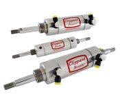
Here's how engineers used advanced software and innovative manufacturing techniques to produce a next-generation, high-flow valve.

Like most everyone today, machine builders want more for less. That certainly holds for users of pneumatic valves, who are clamoring for higher flow capacity, but not at the expense of buying a larger valve. At Clippard Instrument Laboratory, Cincinnati, such demands have spurred the development of a new line of two-way solenoid valves called the DV. Its unique construction builds on technology developed for the company's proven and reliable EV valves. But it provides five to six times more flow in an equally compact design. And, its rated life exceeds 1 billion cycles.

Engineering Challenges
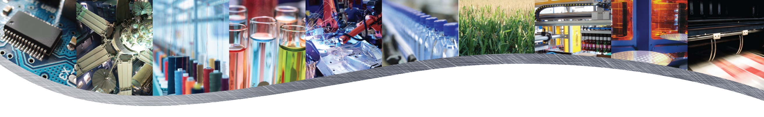
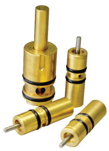
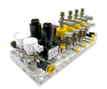
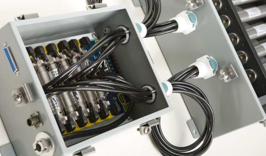
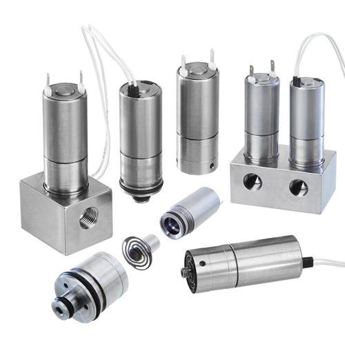
Like its predecessor, the DV consists of three basic subassemblies: housing and solenoid; a base with a nozzle that channels flow; and a "spider" spring assembly that includes a poppet, overmolded seal, and puck-shaped magnet. Development of the DV was challenging, to say the least, admits Clippard Design Engineer Dave McBreen. His objective was upgrading this basic layout to substantially increase flow capacity, without markedly changing the valve's overall dimensions.

Though a serious design constraint, small size is a must because users rely on banks of these valves to handle a variety of tasks, he explains. "They're used in packaging equipment, medical devices, analytical instrumentation, and many other places. Industrial applications typically have multistation manifolds where valves are mounted as close together as possible to minimize space requirements. Thus, the DV valve's OD couldn't exceed three-quarters of an inch."

The first obstacle for the Clippard engineers was designing a solenoid coil that fit the available envelope and could generate sufficient power to shift the valve at high pressures — or determine it was impossible. Product specs called out maximum size, minimum power levels, and maximum flow at standard pressures of 100 psi. And response time had to be in the 10 to 15-msec range to permit high-speed operation.

The question was, how much magnetic force could a coil generate, and how big a magnetic puck was needed to pull against a half-pound preload? "With coil design, it's all about amp-turns," explains McBreen. "You get the most bang for your buck by wrapping out and growing your diameter, as opposed to growing taller." Coil technology hasn't advanced much since the days of the EV's development, so McBreen found no magic bullet in the latest generation of solenoids. "It's still wrapping wire around a spool," he says. They did consider voice-coil actuators, but found them too expensive and with unproven long-term reliability. "It was in our design's best interest to stay with a standard wound coil," says McBreen.

Faced with so many variables, and so many iterations, Clippard engineers developed a Coil Calculator software program to streamline the design process. It let them optimize the coil in relatively short order.

"We're basically designing a bobbin," says McBreen, "and we know the inner and outer diameter of the spool, how tall it is, and the wall thicknesses. The software lets us plug in the geometry and then enter different wire gauges. It shows us how many amp-turns we can get with a 34-gauge wire, a 32-gauge wire, and so on. We key in on the combination that gets us close, then make finite changes to the bobbin geometry to tune it in."

They chose to develop the program in-house, rather than rely on off-the-shelf software, because they had very specific goals. It's like buying an FEA package with lots of options that you don't need, and isn't well suited to your problem, he explains. "The Coil Calculator gave us exactly what we were looking for, it was obviously the way to go."

Engineers used the calculator in tandem with EMS, a 3D electromagnetic field simulator program from Montrealbased ElectroMagneticWorks. It let them tweak the resulting magnetic circuit, with impressive results. "I was shocked at the accuracy," admits McBreen. The first prototype met all physical requirements and performed to within 5% of predictions, which is in line with standard coil tolerances.

Higher Flow
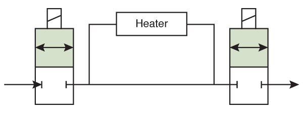
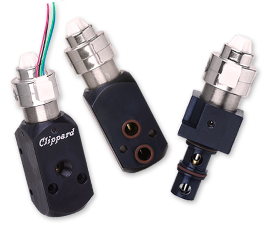
The next engineering hurdle was designing flow passages that upped the valve's capacity, but not its size. "If you look at the nature of a two-way valve, especially a manifold-mount valve, air enters through the bottom, flows into the valve, then makes a 180° turn and travels down through the outlet holes and back into the manifold. That alone creates restrictions that you have to design around, to get the necessary flow," explains McBreen.

They examined many different orifice and channel shapes in the quest to maximize flow. For example, certain nozzle geometries, and radii on the nozzle edges, gave smoother, more-laminar conditions that resulted in consistent and higher flow. An added benefit was lower friction between the orifice and mating nozzle seal, which reduced preload and wear.

DV - How It Works

The DV is a normally closed valve. The poppet with an overmolded seal presses against the nozzle and closes off flow. Energizing the solenoid lifts the magnetic puck towards the core until it bottoms out against the bumper. In the manifold-mount version, air then flows through the #10-32 port, through the orifice, and into the internal chamber. A series of slotted holes surround the molded nozzle, permitting air to flow out to the manifold.

Engineers relied on both computational fluid dynamics analysis, in this case Flow Simulation CFD from Dassault Systémes SolidWorks, based in Waltham, Mass., as well as on physical testing—validating concepts with machined prototypes. CFD proved to be an excellent tool for modeling flow through individual valves and examining various options, says McBreen. However, simulating a bank of manifold-mounted valves was rather time consuming, he admits, as there are so many pathways to consider.

Spider Spring
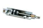
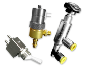
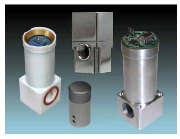
Perhaps the most visually interesting component within the DV is the spider, an unusual spring that shifts the valve when the solenoid deenergizes. Developed by Clippard engineers, the unique configuration lets it generate sufficiently high force from an extremely compact spring with very little movement—the DV has only 0.018 in. of stroke and about 0.018 in. of spring preload. Minimal stroke is necessary, says McBreen, to ensure precise control and maximum flow at operating frequencies as high as 32 Hz.

Getting the configuration just right required intensive FEA analysis in SolidWorks on various spider designs. "We wanted the legs as long as possible, to get the longest stroke within our space limitations," says McBreen. Thus, the number, shape, length, and layout of the legs, the radii of transitions, and many other factors were studied and adjusted to come up with the proper stroke and spring rate—while keeping stress levels sufficiently low to ensure extremely long life.

The spider spring, with its long, narrow and curving legs, would be difficult to machine or fabricate by stamping, but it is pretty simple to etch, he notes. The process starts with a flat sheet of 0.020-in.-thick 17/7-PH stainless steel, which is then chemically etched to the final configuration. A finishing operation removes stress risers and gives it a glasslike surface. The process holds tolerances on some features to ±0.001 in., so there is little variation from part to part. That helps ensure consistent performance from one valve to the next.

Testing, Testing
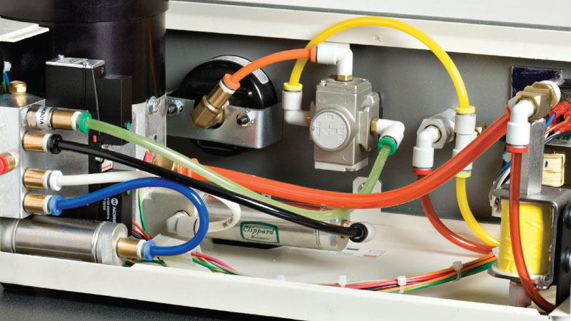
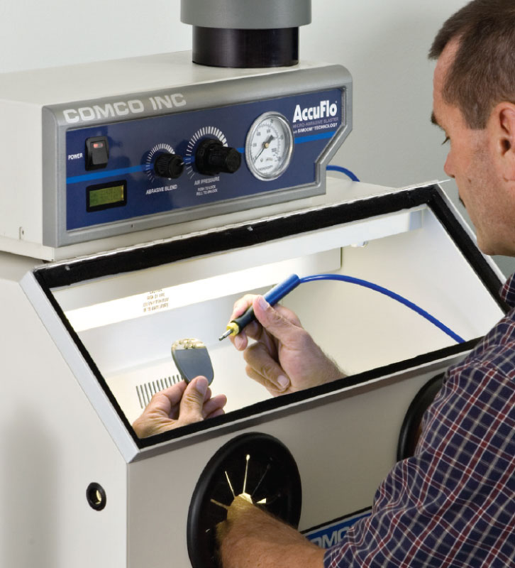
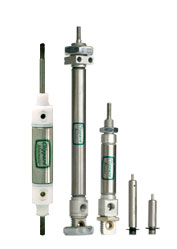
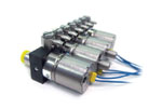
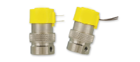
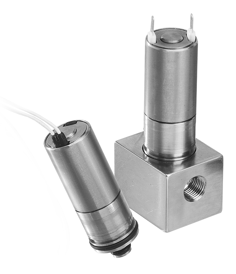
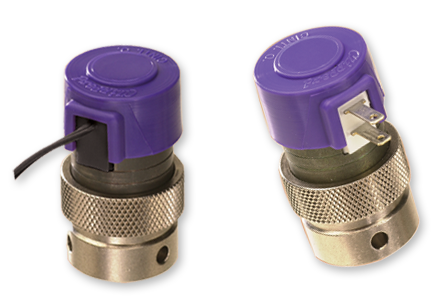
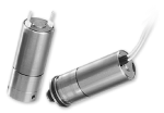
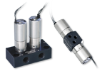
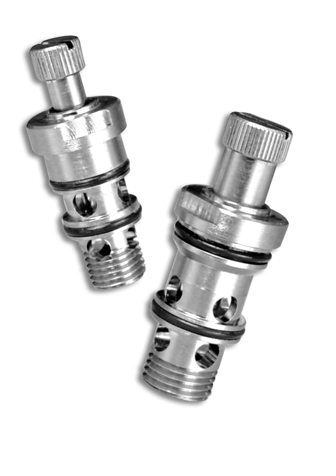
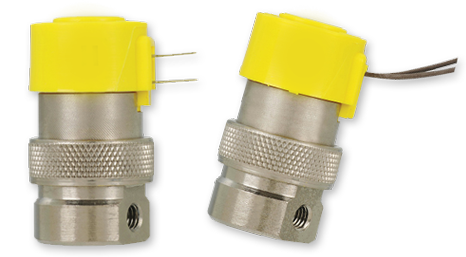
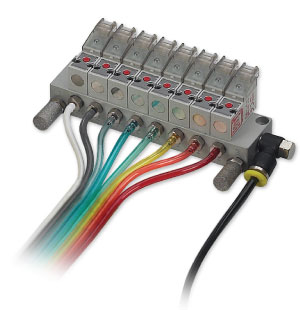
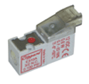
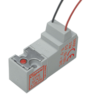
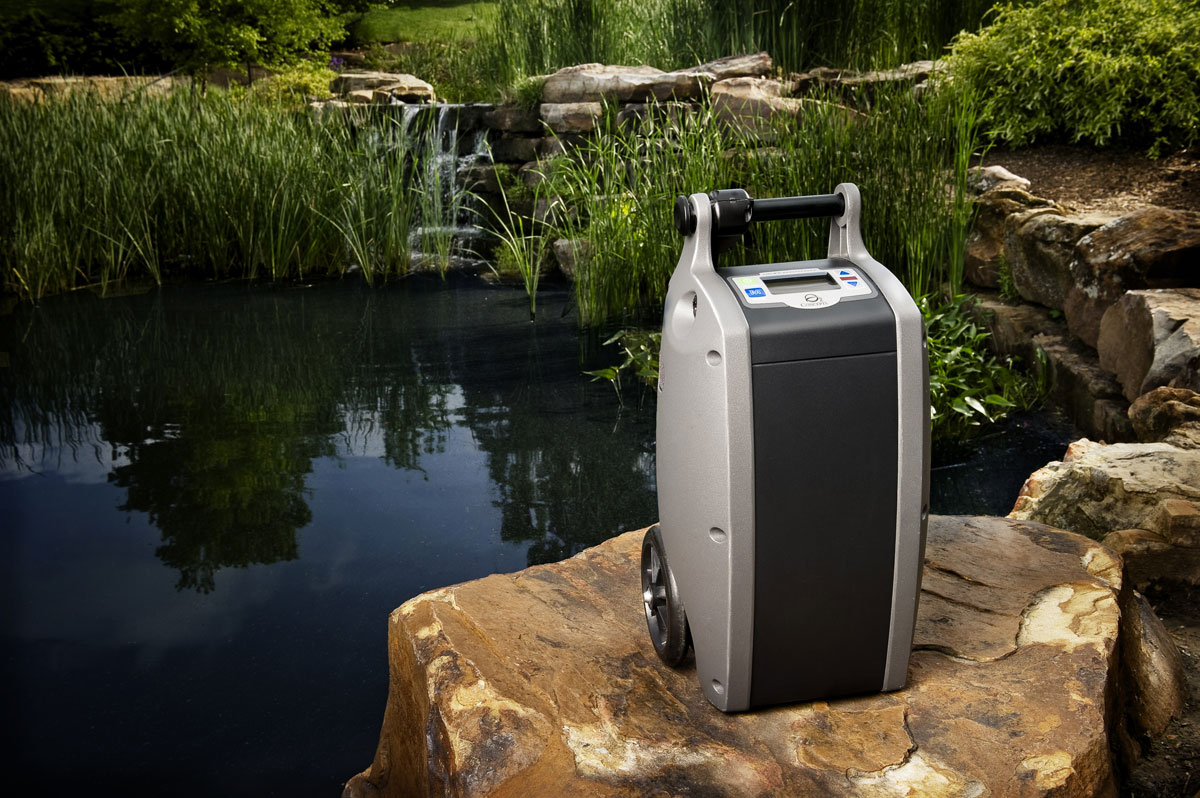
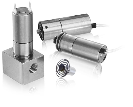
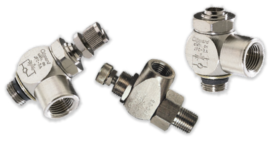
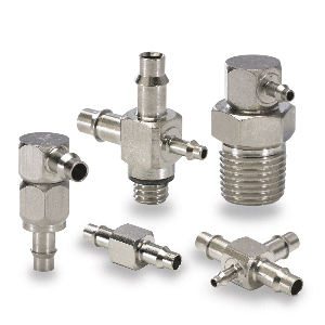
Engineers tested several evolutions of the valve to prove out the design, evaluate different manufacturing techniques, and ensure the DV's durability. And given the billion-cycle intended life, that required some patience—as it involves running the valves at 32 Hz and 24/7 for a year. The test rig required solid-state relays because mechanical contactors would burn up under such demanding conditions. Units are tested at various pressures ranging from 0 to 100 psi, response time was regularly monitored, and valves were checked for leaks and seal wear every 50 million cycles.

McBreen's main concern was that the overmolded poppet seals would peel off the base metal over time, but that was never an issue. However, one unforeseen dilemma on an early prototype was the appearance of fretting corrosion between the magnetic puck and housing.

The initial design mandated an extremely small gap between the two parts, to take full advantage of the available magnetic field, McBreen explains. "Apparently, it was a bit too close."

DV Series

The compact DV is a two-way solenoid valve that provides five to six times the flow of previous versions.


DV Series

The spider spring shifts the valve when the solenoid deenergizes and has a stroke of only 0.018 in.

Fixing the problem wasn't a simple as merely widening the gap, however. "If you make the clearance too big, then you lose a percentage of your magnetic force." He again turned to the EMS software to refine dimensions and ensure the puck stays centered and glides with minimal friction—all while maintaining the needed magnetic-field strength.

Such setbacks are inherent to engineering, says a pragmatic McBreen. "It's part of the optimization process. Analysis only shows you so much and gets you in the right ballpark. That's why you test it, to find out what relative changes you can make to improve the end product."

Manufacturing Issues
Because the DV has a number of working components, and an extremely short stroke, part tolerances could have been a nightmare. "If you're not careful, the tolerance stack-up will match the stroke and the valve won't work. The battle is how to control those tolerances without driving manufacturing costs through the roof," states McBreen. "It gets a little tricky, but there are certain features we can control very tightly, so it eliminates some of the stack," he says. That's why parts are manufactured at Clippard's facilities in Cincinnati. "One of our niches is being very good at machining parts with very tight tolerances. We have the right equipment, we've been doing it for a long time, and it's less costly than using outside vendors."

Ensuring the DV is easy to manufacture and assemble was also a prime concern from the beginning. One example McBreen cites is opting for a molded nozzle, versus a machined one. Machining small orifices in stainless steel and holding extremely tight tolerances is difficult, and the parts take too long to make. Instead, a key supplier molds the nozzles from dimensionally stable Ultem and holds ±0.001 in. on the ID and other critical dimensions. And they tightly control the process to ensure excellent repeatability, he says.

The plastic nozzle also lets manufacturing personnel pop in a radial seal by hand, and it seats against the housing and nests in proper relation to the spider. The subassembly gives the necessary preload with near-zero friction on liftoff.

Assembling the DV involves simple press fits with no shimming. The three subassemblies are put together using simple tools, and every valve is automatically tested prior to shipping to the customer. Compared to the EV valve, the DV's streamlined manufacturing procedures save several minutes of production time for each part – which adds up to sizable time savings in highvolume production.

Product Specs
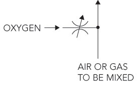
The DV is rated for flows of 100 lpm at 50 psi with a 0.070-in. orifice, and 100 lpm at 100 psi with a 0.052-in. orifice.

It's suitable for service with air and other compatible gases, and it is currently being tested with water. The valve base is made of 303 stainless steel, and all the magnetic components are 430F stainless steel. Other "wetted" materials include Ultem and polyphenylene sulfide (PPS). Ultem is a thermoplastic polyetherimide resin with outstanding elevated thermal resistance, high strength and stiffness, and broad chemical resistance. PPS, in similar fashion, has outstanding chemical resistance as well as thermal and dimensional stability. Seals in the DV are typically Buna, but FKM, silicone, and EPDM are available on request.

The valve has rather large flow passages and is quite dirt tolerant, says McBreen. It runs fine on air filtered to 40 μm and offers an important user-friendly feature: the valve is easy to disassemble and clean.

Control voltages are typically 12 and 24 Vdc, but many users design their own circuitry. One example is hit/hold actuation which energizes the valve momentarily with its rated voltage, and then reduces it by approximately 33% to hold the valve position. Some even run off rectified alternating current. Rated power consumption is 1.9 W.

Both manifold and cartridge mounting options are offered, and the valve has #10-32 ports and a 0.75-in. body. Clippard is also producing a metric version for marketing worldwide. It has M5 ports and a 19-mm body.

Markets & Applications
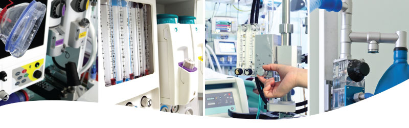
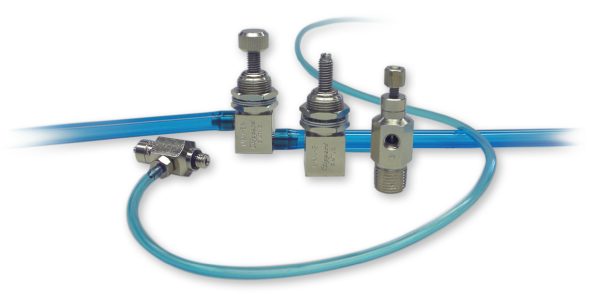
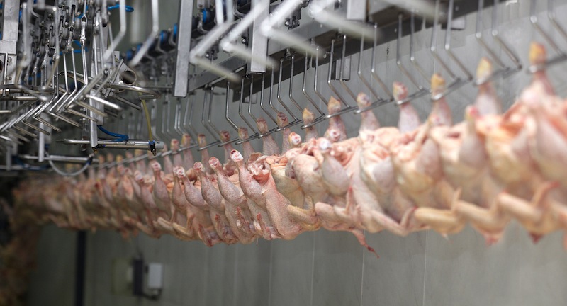
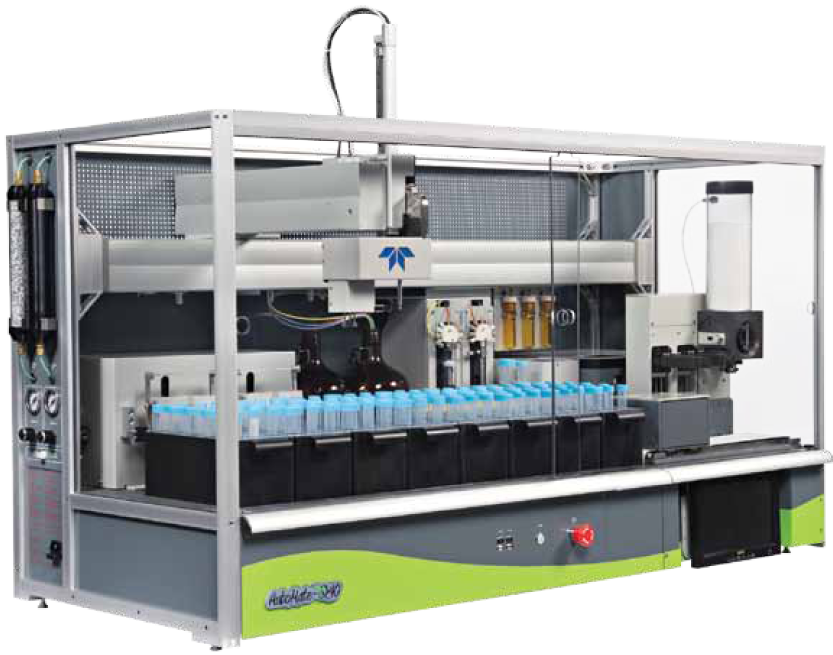
DV valves are suitable for many applications across a diverse range of industries. "We feel it's a very optimized valve," stresses McBreen. "It has a small package, with little heat rise, and low power consumption. They mount on three-quarter-inch centers, can flow a lot of air, and they're very price competitive."

He ticks off a list of potential applications, such as in medical devices like blood-pressure cuffs, for analytical instrumentation, gas chromatography, and leak-decay test systems. In manufacturing settings, banks of valves are well suited for controlling production machines and packaging operations—applications that tend to have lots of cylinders and actuators.

A fully ported three-way version of the DV is slated for introduction this fall, and a proportional valve is in the works.


Enter the Scary Door... If You Dare!

$
0
0
Category: 


Design News


OCTOBER 2013
Design Hardware & Software
BY CABE ATWELL

Halloween is a time when kids and adults get the opportunity to step outside themselves and dress up in attire that would be deemed strange any other time of the year.

These attractions sure have come a long way from those back in the '80s when I was growing up. Back then, kids used their imaginations as we ventured through the local haunted houses, which were usually erected in a shopping plaza's parking lot. These were the kind that wwere built into several semi-trailers that were usually connected together to form several rooms.

The Raspberry Pi & air piston-based Scary Door.
Source: Cabe Atwell

The rooms were then outfitted with terrifying glow-in-the-dark ghosts, rubber serpents and spiders, and a host of teenagers made up to look like goblins that were going to drag us to their chamber of horrors.

The technology that made up those attractions is not in the same league as those found in cities across the U.S. in the 21st century. Most of the technology back then consisted of levers and pulleys that would move objects using fishing line. Sure, that’s not so scary, but factor in black lighting and strobe lights, and things seemed pretty frightening, especially being 12 to 14 years of age.

Fast-forward to today’s multi-million dollar haunts, and the difference in technology is night and day. The pulleys and fishing line have been replaced with pneumatic actuators that allow finely-detailed monsters to move. Gone are the simple black lights -- they’ve been replaced with IR (infrared) sensors and precision lasers that are able to detect movement and activate horrific props as patrons walk by.

All the technology these places feature (on a large scale) are controlled by a central hub or computer system, which controls everything from haunting sounds to incredibly realistic animatronic displays. For some of the bigger venues, fans are required to sign waivers as they proceed through the attraction, as well as required to wear an RFID bracelet that not only lets supervisors know your location, but are also used to trigger some of the displays themselves. Technology isn’t just centered on large attractions alone -- home-brew haunted houses are taking advantage of it as well.

My Scary Door project is a prime example of how new technology is being implemented in at-home attractions. The door was designed using a 24-inch monitor that displays Halloween-themed videos embedded in a creepy sheet-metal laden door. Outfitted behind the door is a system of pistons and solenoid valves that strike the sheet metal in time with the video being displayed to create the simulation that someone (or something) is beating on the door. Trick-or-treaters engage the door’s scariness by triggering a Seco-Larm Enforcer break-beam device situated several yards before getting to the door itself. Controlling the show are two Raspberry Pi SBCs, with one for controlling the video output and the other, combined with a PiFace, for implementing the relays that fire the pistons. C and C++ code bind everything together for a technology-based haunted device that is capable of scaring the most reserved children looking to get their Halloween candy.

It’s easy to understand why scaring people is big business, as the revenue generated each year for these haunted attractions can easily be in the billions. This creates healthy competition for those who design such attractions to be the scariest in the nation. It’s most assured that as technology advances, so will our fears, which seem to grow as Halloween draws near and we venture through the “Scary Door”!

Happy Halloween!


How to Use a Clippard Cylinder to Boost Your Post-Thanksgiving Workout

$
0
0
Category: 

We hope you have a great Thanksgiving, with lots of turkey and pumpkin pie! Don't worry about eating too much, we've got you covered. For those of you tracking your health and fitness, you'll find it's an easy, efficient way to give yourself the post-Thanksgiving boost you need. Grab yourself a Clippard cylinder and check out this useful application, courtesy of aerospace engineer Howard Wolowitz.


Related Products:

Stainless Steel
Cylinders


Stainless Steel Cylinders
All Stainless
Steel Cylinders


All Stainless Steel Cylinders
Fittings, Hose
&Tubing


Fittings, Hose and Tubing


Miniaturization Makes Pneumatics the Choice in Medical Applications

$
0
0
Category: 

From ambulance to operating room, recovery room to discharge at home, patients today encounter any number of medical devices that must be lightweight, small, safe, and often, portable. To maintain these safe, hygienic designs, most medical device manufacturers rely on pneumatics because they are highly customizable and compact.


As the demands for these types of components have evolved, so have the pneumatic cylinders and valves used in them. The need for smaller, lighter devices has translated into a push for valves that offer more flow at lower power (often battery power). In addition, this all means the need for lighter materials, so plastic has grown in use, said Bonnie Martens, marketing communications specialist at Kalmazoo, Mich.-based Humphrey Products.

"The need for increased flow from smaller valves at lower power is driving the change in the solenoid valve arena," said Martens. "Additionally, the need for quiet valves is also driving these new designs."

Rob Clippard, vice president of sales and marketing at Clippard Instrument Laboratory, Cincinnati, added that Clippard innovated the internal workings of these innovative pneumatic valve designs. "Clippard is the benchmark for valve technology used in medical devices. Our spider design or flat armature spring element provides a valve that is quiet, fast, reliable, and has exceptional life," he said.

The need for higher flows and lower power consumption was what drove Clippard to redesign its benchmark valve design, coming up with its new DV valve, which offers flows up to 100 L/min and only consumes 1.9W in power. Additionally, Clippard said that the company also offers power saving circuits and latching valves in applications where low power use is critical.

Adaptation is critical

Pneumatics is used heavily in oxygen concentrators, infusion pumps, ventilators, wound therapy, blood analyzers, pressure cuff devices, medical bed surfaces, breathable gas delivery systems and anesthesia devices because they all use some type of gas to control their functions.

But because pneumatic components were initially designed for industrial use, manufacturers have had to adapt their use to medical designs. "The challenge is making an industrial-grade product work in a medical device because their needs are different than industrial applications," said Paul Gant, sales manager at AVENTICS, the newly branded company that was formerly Bosch Rexroth's pneumatics division, based in Lexington, Ky.

However, this forced adaptation has allowed for some unique innovations because there aren't a great deal of regulations or standards that restrict design, Gant added. Although RoHS, REACH and ISO standards are critical to design, there is no one rule to follow. "If you come up with a pretty good idea, there's not a lot of history or regulations that tie you from using that product," Gant said.

Clippard added that adjustments to standard products are application specific. "For example, increasing pressure on the blood pressure monitoring cuffs now would allow you to market your product as a tourniquet," Clippard said, concluding that most medical device manufacturers are looking for partners that can help them simplify their design and manufacturing process.

Custom applications

In the majority of cases, the relationship between pneumatics companies and medical device manufacturers becomes an engineering partnership.

For example, Humphrey was recently recognized for its work with Stryker Medical. Stryker was honored with a 2014 Medical Design Excellence Award through the Medical Device and Diagnostic Industry for its newest hospital bed technology—the Isolibrium critical-care air support surface. The goal of the device is to serve as a tool for nurses to care for patients while the pressure redistribution system helps prevent pressure ulcers in patients. Humphrey was recognized as a "supplier to a winner" for its efforts in the design of the pneumatic controls portion of the Isolibrium Surface.

In another application, Humphrey's custom valve assembly enabled a respiratory care manufacturer to provide critical pressure monitoring when delivering a CO2-O2 mixture to patients suffering from toxic gas or smoke inhalation.

Gant said AVENTICS' key involvement is with oxygen concentrators. Meeting the low-pressure needs of portable oxygen concentrators (POCs) was a challenge, he said. These portable designs were reduced from 10 lb to about 2 or 3 lb, so adapting an industrial valve to this smaller, lighter weight design required some product redesigns. In industrial settings, pilot-operated valves operate at about 40 psi to open a larger valve. But these medical devices were operating at pressures in the range of 3 to 7 psi.

"One of our challenges was to reduce the operating pilot pressure and still use a dual-stage valve, which gives you high flow, but have it operating at less than 6 or 7 psi," Gant said. "To accomplish this, we used polycarbonate bodies that we designed to maximize the area of the operating valve."

As he explained, the physics of fluid power is simple—the pressure to open something is based on the size of what you're pushing. In most valves, the actual operating element is tiny compared to the valve body. "What we needed to do was make the body smaller and the operating element a larger portion of that whole percentage," Gant concluded.

Getting into the Internet of Things

Automation and diagnostics have become a critical part of medical devices, and increasingly, pneumatic components are supporting this need for data transmission, said Gant.

"What this means for pneumatics, is that if the machine is going to get more automated, the pneumatic devices change slightly to where something that might have been a manual device—a toggle valve or something like that—now suddenly has to be electronic and guided by a PLC or motherboard," Gant described, saying that things like pressure control must be electronic and changeable depending on what the device is."

"Theoretically, the more information they have, the more they can tailor your treatment to you. It gives you the best care, but that also means, perhaps, less procedures and less hospital care because more things can be done through the better diagnostics," Gant concluded. "All of these things lead to better personalized healthcare."

Design World
Original Article, October 2014
By Mary Gannon


Automated Spool Valve Assembly Machine Increases Efficiency, Boosts Capacity

$
0
0
Category: 

Clippard has years of experience manufacturing valve components with automated CNC machines that have the capacity to run lights out 24/7. This gives Clippard repeatable performance, consistent quality, lower cost, and higher capacity. Over the past year, Clippard has developed several new automated machines to bring these same benefits to the assembly side of the company's operations.

One of these such machines is this Automated Spool Valve Sub-Assembly Machine. As assembly staff heads home to be with their families, this machine continues building spool valve sub-assemblies for Clippard's popular MAV, MJTV and FV Series spool valves. These components will be assembled overnight, ready for the final product assembly in the morning.

Clippard's Automated Spool Valve Sub-Assembly Machine utilizes a variety of Clippard automation components, including stainless steel cylinders with GMR switches, flow controls, customized pinch valves, Maximatic® FRLs and valve banks, along with Clippard fittings and tubing, in combination with an Epson robot and a Horner PLC.

Clippard cylinders are integral in the automation of a variety of tasks, including dispensing the valve spools and transferring the o-rings into position. Brian Kettering, Electro-Mechanical Automation & Robotics Technician for Clippard Instrument Laboratory, explains, "Clippard cylinders with GMR switches transfer the o-rings from a feeder track onto a mandrel, and feed the spools from a bowl into a nest to be picked. When a part is sensed, the cylinder retracts back into position and waits for the robot to finish its cycle."

"These machines improve efficiency and consistency in our assembly department," says Kettering. "They boost our capacity and improve the quality of our products without increasing cost."


Related Products:

Stainless Steel Cylinders

Clippard Stainless Steel Cylinders
GMR Switches

Magnetic Switches
Flow Controls

Flow Controls
FRLs

Clippard Stainless Steel Cylinders

10 mm Valves

10 mm Electronic Valves
15 mm Valves

15 mm Electronic Valves
Fittings

Minimatic Fittings
Hose & Tubing

Clippard Hose & Tubing


Unique Anti-Roll System Gives Hybrid Car Competitive Edge

$
0
0
Category: 

A team of engineering students at the University of Victoria recently developed a unique system utilizing Clippard pneumatic cylinders to give their hybrid car a competitive edge by reducing body roll during cornering.

UVic Hybrid CarClippard Cylinders in UVic Hybrid Car

Anti-roll bars are conventionally employed to reduce body roll during cornering and allow tuning of handling properties. A typical anti-roll bar is simply a bent steel tube that acts a torsional spring between the two sides of the car in the front and the back.

The UVic car was designed with a more novel solution, utilizing Clippard double-acting cylinders on each corner of the car. The upper chamber of each cylinder—with respect to the car—is considered the positive chamber and the lower the negative. The positive chamber on one side is linked directly to the negative on the other side with a valve on the line to allow filling. Both lines are set to the same pressure. When both wheels move up, such as when the car dives under braking or goes over a speedbump, the positive chambers of both sides shrink at the same rate as the negative chambers grow and there is no pressure change. However, when the car rolls the positive chamber on one side grows while the positive chamber on the other side shrinks. This creates a big pressure differential and prevents the car from rolling past a small amount.

UVic Hybrid Team Wins First Place

The UVic Hybrid Team's system has proven to be hugely effective, allowing them to trim their car's body roll to near zero. Unlike conventional anti-roll bars which have to be unbolted and moved to adjust rates, UVic's system is easily adjustable using a small hand pump to set the pressures. This is a big benefit, as it allows very fast adjustment on the track.

The team's efforts paid off, winning them first place in the hybrid category at the 2016 Forumula Hybrid Competition. They also won three other significant design awards, including a perfect score in the prestigious design review event.

Congratulations to the UVic Hybrid Team!


The UVic Hybrid Team is a group of UVic engineering students that design, build and compete with hybrid vehicles. Their vehicles challenge the status-quo of hybrid vehicle technology, with performance and efficiency far above conventional vehicles.


Related Products:

Stainless Steel
Cylinders


Stainless Steel Cylinders
All Stainless
Steel Cylinders


All Stainless Steel Cylinders
Fittings, Hose
&Tubing


Fittings, Hose and Tubing


Ghostbusters Rely on Clippard

$
0
0
Category: 

The Proton Pack is a piece of particle accelerating machinery created by Egon Spengler and used by the Ghostbusters. It is their primary tool in the 1984 & 1989 Ghostbusters films for "busting" ghosts. It has a hand-held wand ("Neutrona Wand" as scripted by Dan Aykroyd) connected to a backpack-sized cyclotron. The theory is that it fires a 'semi-controlled' stream of protons that neutralizes the negatively charged electromagnetic radiation of a ghost allowing it to be held in the active stream.  This systems rely on the high quality and reliability that Clippard provides.  Some products used are the R-701 regulator, the R-341 Delay valve and several other brass fittings and tubing.


The props representing proton packs were created by the prop department at Columbia Pictures. They are made of molded fiberglass shells on aluminium backplates (or "motherboards") bolted to military surplus A.L.I.C.E. pack frames. The basic shape was sculpted from foam; later, a rubber mold was made, from which fiberglass shells were pulled. The "wand" had an extending barrel mechanism and the electronics were quite advanced for the time. They were then finished with various surplus 1960s resistors, pneumatic fittings, hoses and ribbon cable, as well as surplus warning labels and custom-made metal fittings. The overall weight of these props is said to be around 35lbs. The "hero" props were substituted in stunt scenes by flimsy foam rubber pulls from the same mold. The proton packs have a lightbar with 15 blue scrolling lights in a box on the left-hand side and 4 red lights in the circular "cyclotron" portion of the bottom of the prop that light up in rotation. The "wand" also featured numerous light features; the most elaborate versions had fluorescent bargraphs, incandescent bulbs, and strobing flashes in the tip for the visual effects crew to synchronize the famous 'streams'. 

Ref: http://www.gbfans.com
"Ghostbusters" are registered Trademarks of Columbia Pictures Industries Inc.

Viewing all 132 articles
Browse latest View live